Volkswagen EA288 Series, Sensor Locations For 2.0L TDI and 1.6L TDI Diesel Engines
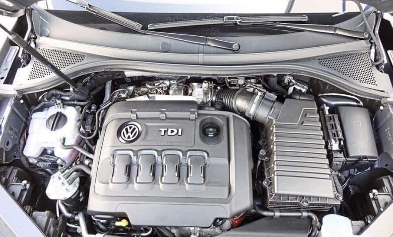
Installation locations of sensors and elements of the injection system for the 4-cylinder diesel engines 1.6 and 2.0 litres, Common Rail, Volkswagen EA288 series
Volkswagen EA288, Engine Code :
DCYA, DDMA, DFGA, DFGB, CRFC, CYKB, DFHA, DCYB, DGDB, DBGA , CRGA, DFGC, CYKC, DBGC, CRGB, CRFZ, CRFD, DGTE, DFFA, DGTC, DGTD.
- VW Polo 6 (AW1) from 2018,
- VW T-Cross (C11) from 2019,
- VW T-Roc (A11) from 2018,
- VW Tiguan (AD1) from 2016, V
- W Tiguan RUS (BT1 ) since the 2017 release.
Also, these engines are installed on:
- VW Passat B8 (3G),
- VW Arteon (3H7),
- VW Golf 7 (5G1, BV5, BQ1),
- VW Golf Sportsvan (AM1, AN1),
- VW Touran 2 (5T1),
- Skoda Karoq (NU7 ),
- Skoda Octavia 3 A7 (5E3, 5E5, NL3),
- Skoda Kodiaq (NS7),
- Skoda Superb III (3V3, 3V5),
- Audi A3 (8VK, 8VF, 8VE, 8VM),
- Audi Q2 (GAB), SEAT Ibiza 5 (KJ1),
- SEAT Arona (KJ7),
- SEAT Ateca (KH7),
- SEAT Leon 3 (5F), etc.
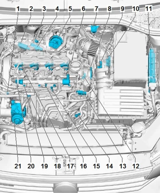
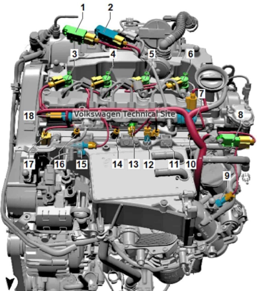
Overview of installation locations – injection system for diesel engines 1.6 and 2.0 series Volkswagen EA288
1 – Cylinder head coolant valve N489
2 – Differential pressure sender G505; is installed depending on which emission standard the vehicle complies with.
3 – The NOx sender G295; is contained in the control unit for the NOx sender GX30 together with the control unit for the NOx sender J583
4 – Exhaust gas pressure sender 1 G450
5 – Position sender for charge pressure sender G581
6 – Fuel pressure control valve N276
7 – Control solenoid valve boost pressure control N75; Connector for boost pressure control solenoid valve N75.
8 – Camshaft inlet valve 1 N205
9 – Air mass meter G70; with intake air temperature sender G42.
10 – The NOx sensor control unit J583; is contained in the GX30 NOx sensor control unit together with the NOx sensor G295
11 – Engine control unit J623
12 – Coolant outlet cooler G62
13 – Charge air pressure sender G31
14 – Charge the air temperature sender in front of the aftercooler G810
15 – Charge the air temperature sensor after charging air cooler G811
16 – Hall sender G40; Camshaft position sensor
17 – Injectors
- Injector, cylinder 1 N30
- Injector, cylinder 2 N31
- Injector, cylinder 3 N32
- Injector, cylinder 4 N33
18 – Fuel temperature sensor
Depending on the vehicle model, different types of sensors can be installed.
Fuel temperature sender G81
Temperature and pressure sender for the low-pressure fuel system GX20
19 – Glow plugs Glow
plug 1 Q10
Glow plug 2 Q11
Glow plug 3 Q12
Glow plug 4 Q13
Depending on the vehicle model, a pressure sensor in the combustion chamber is built into the glow plug.
- Glow plug 1 Q10 with combustion chamber pressure sensor cylinder 1 G677
- Glow plug 2 Q11 with combustion chamber pressure sensor cylinder 2 G678
- Glow plug 3 Q12 with combustion chamber pressure sensor cylinder 3 G679
- Glow plug 4 Q13 with combustion chamber pressure sender for cylinder 4 G680
20 – Fuel pressure sender G247
21 – High-pressure pump; with fuel metering valve N290 (do not open)
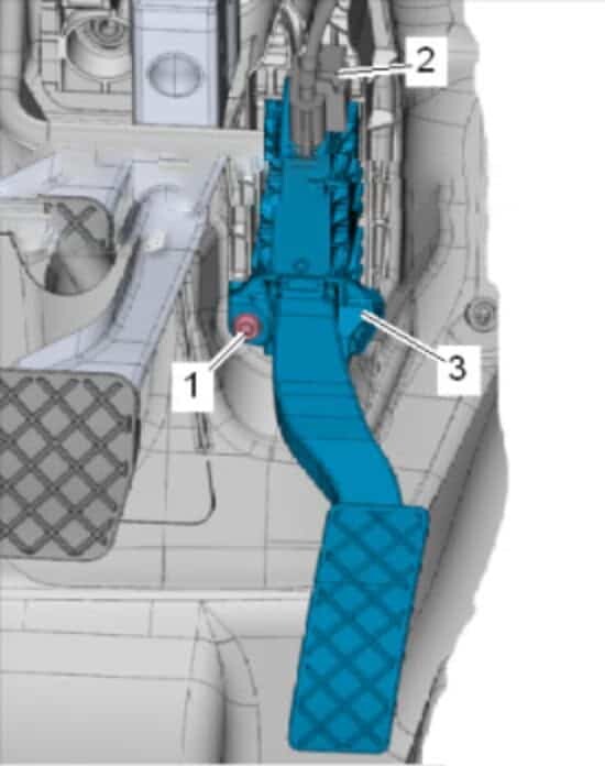
Accelerator position sender G79 and accelerator position sender 2 G185
The accelerator position sender G79 and the accelerator position sender 2 G185 are located in the accelerator pedal module GX2.
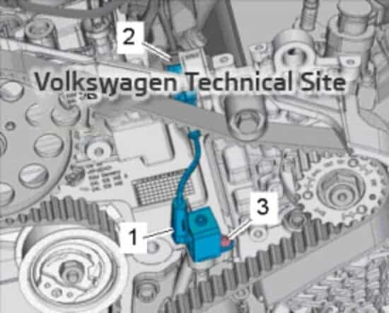
The installation location of flap control unit J883
Fitting location of coolant valve for cylinder head N489
Exhaust gas recirculation cooler changeover valve N345 -1-
Not suitable for all vehicles
Overview of mounting locations on the engine (top)
1 – Differential pressure sender G505; Installed depending on which emission standard the vehicle complies with.
2 – Exhaust gas pressure sender 1 G450
Depending on the vehicle
3 – Injector, cylinder 1 N30
4 – Injector, cylinder 2 N31
5 – Injector, cylinder 3 N32
6 – Injector, cylinder 4 N33
7 – Fuel pressure control valve N276
8 – Pressure sensor Charge air temperature sensor G31
9 – Charge air temperature sensor in front of the charge air cooler G810
10 – Glow plug Glow plug
4 Q13; Depending on the vehicle model, the combustion chamber pressure sensor is integrated into the glow plug. Combustion chamber pressure sensor cylinder 4 G680
11 – Glow plug Glow plug
3 Q12
Depending on the vehicle model, the combustion chamber pressure sensor is integrated in the glow plug.
Combustion chamber pressure sender, cylinder 3 G679
12 – Charge air temperature sender after aftercooler G811
13 – Hall sender G40
14 – Glow plug Glow plug
2 Q11
Depending on the vehicle model, a combustion chamber pressure sender is integrated in the glow plug.
Combustion chamber pressure sender, cylinder 2 G678
15 – Fuel temperature
sender Depending on the vehicle model, different types of senders can be fitted.
Fuel temperature sender G81
Low-pressure fuel system temperature and pressure sender GX20
16 – Glow plug Glow plug
1 Q10
Depending on the vehicle model, the combustion chamber pressure sensor is integrated into the glow plug.
Combustion chamber pressure sender in cylinder 1 G677
17 – Cylinder head coolant valve N489
18 – Fuel pressure sender G247
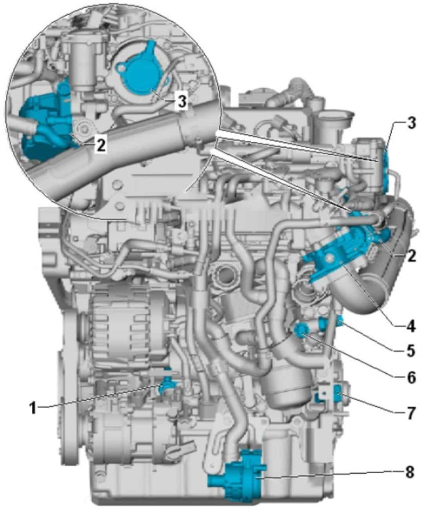
Overview of installation locations – engine front view
1 – Oil pressure control valve N428
2 – Exhaust gas recirculation valve 1 GX5; With exhaust gas recirculation potentiometer G212; With exhaust gas recirculation control motor V338
3 – Inlet camshaft valve 1 N205; Depending on the vehicle
4 – Throttle valve module J338; With throttle potentiometer dampers G69
5 – Oil pressure sender for oil pressure reduction F378
6 – Oil pressure sender F1
7 – Engine speed sender G28
8 – Charge air cooling pump V188
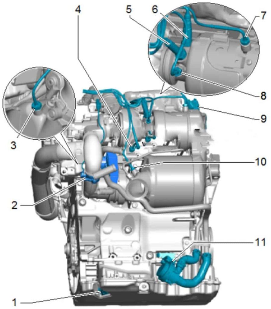
Overview of installation locations – rear view of the engine
1 – Oil level and oil temperature sender G266
2 – Exhaust gas recirculation valve 2 GX6, With EGR control engine 2 V339, With exhaust gas recirculation potentiometer 2 G466
3 – Exhaust gas recirculation temperature sensor G98, Vehicle Specific, 45 Nm
4 – Exhaust gas temperature sensor 1 G235
5 – NOx sender control unit GX30
Contains NOx sender G295 and NOx sender control unit J583
6 – Lambda -probe 1 to catalytic converter GX10, Consisting of lambda probe G39 and lambda probe heater Z19, 52 Nm
7 – Exhaust gas temperature sender 3 G495
8 – Exhaust gas temperature sender 2 G448
9 – Reductant injector N474
10 – Exhaust gas temperature sender 4 G648
11 – Auxiliary heater pump V488
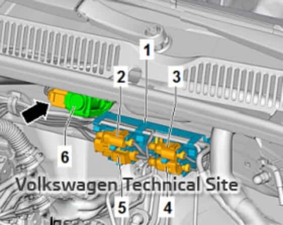
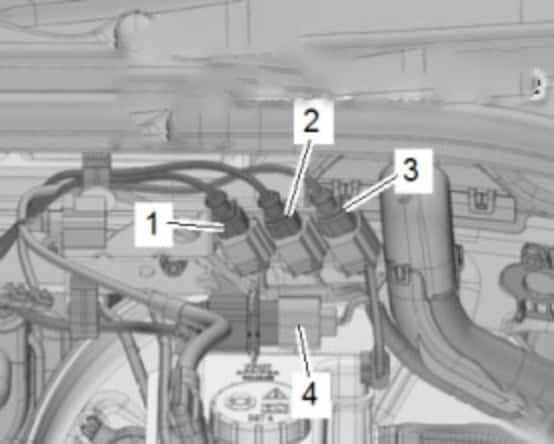
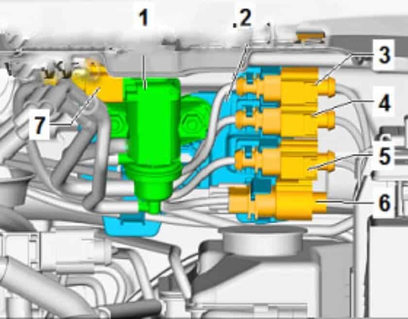
Overview of installation locations – electrical connections
VW Tiguan 2:
1 – Bracket
2 – Exhaust gas temperature sender 3 G495 – brown plug
3 – Exhaust gas temperature sender 2 G448 – black plug
4 – Exhaust gas temperature sender 4 G648 – beige plug
5 – Lambda probe 1 to GX10 catalytic converter – black plug
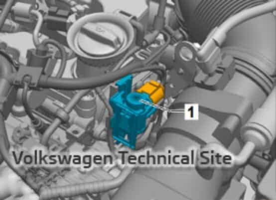
6 – Solenoid valve for boost pressure control N75
VW T-Roc, VW T-Cross:
1 – Exhaust gas temperature sender 4 G648 – beige connector
2 – Exhaust gas temperature sender 3 G495 – brown connector
3 – Exhaust gas temperature sender 2 G448 – black connector
4 – Lambda probe 1 before catalytic converter – GX10
VW Polo 6:
1 – Solenoid valve for charge pressure control N75
2 – Bracket
3 – Exhaust gas temperature sender 2 G448 – black connector
4 – Exhaust gas temperature sender 3 G495 – brown connector
5 – Exhaust gas temperature sender 4 G648 – beige connector
6 – Lambda probe 1 to catalytic converter GX10 – black connector
7 – connector for boost pressure control solenoid valve N75, connector colour black


