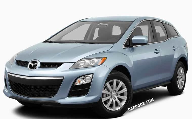
2006-2012 Mazda CX-7 Fuse box diagram, location, rating and replacement
Mazda CX-7 Fuse Box Diagram: Dashboard fuse box
It is located at the bottom of the dashboard on the driver’s side, behind the protective cover. Pull the cover towards you to access it.

Type 1
Diagram
Assignment
| 1 | 15А OUTLET 1 – Additional electrical outlet in the cabin, cigarette lighter |
| 2 | 15A OUTLET 2 – Additional electrical outlet in the trunk |
| 3 | 7,5А P.MIR – Mirror with electric drive |
| 4 | 30A WIPER – Cleaner and washer of a windshield |
| 5 | 7.5A M.DEF – Heated mirror |
| 6 | 7,5А ENG BAR 3 – Air flow meter, EGR valve |
| 7 | 15A P.WIND – Electrically operated glass lifters |
| 8 | 7.5A A / B – Passive safety system, Airbags |
| 9 | 15A ENGINE – Engine management system |
| 10 | 10A METER – Instrument cluster |
| 11 | 5A BBS – Security structure |
| 12 | 15A ROOM – Interior lighting, Audio system |
| 13 | Reserve |
| 14 | 10A ILLUMI A / C – Illumination of the instrument panel |
| 15 | 20A SEAT – Heated seat |
| 16 | 10A A / C – Air conditioner |
| 17 | 10А R.WIP – Wiper and washer of rear window |
| 18 | 10А R.FOG – Rear fog lamp |
The fuses numbered 1 and 2 at 15A are responsible for the operation of the cigarette lighter.
Type 2
Diagram

Protected components
| 1 | 30A P.WIND2 – Electrically operated glass lifters |
| 2 | 15А OUTLET 1 – Additional electrical outlet in the cabin, cigarette lighter |
| 3 | 7,5А P.MIR – Mirror with electric drive |
| 4 | 15А OUTLET 2 – Additional electrical outlet |
| 5 | Reserve |
| 6 | 30A WIPER – Cleaner and washer of a windshield |
| 7 | 7.5A M.DEF – Heated mirror |
| 8 | 7,5А ENG BAR 3 – Air flow meter, EGR valve |
| 9 | 15A P.WIND – Electrically operated glass lifters |
| 10 | 7.5A A / B – Advanced passive safety system, airbags |
| 11 | 15A ENGINE – Engine management system |
| 12 | 15A METER – Instrument cluster |
| 13 | 10A ILLUMI – Illumination of the instrument panel |
| 14 | 15A ROOM – Audio system, upper interior lighting |
| 15 | 20A SEAT – Heated seat |
| 15 | R.FOG – Rear fog lights |
| 16 | 10A A / C – Air Conditioning |
| 16 | SIREN – Security alarm |
| 17 | 20A SEAT – Heated seats |
| 18 | 10A A / C – Air Conditioning |
| 19 | 10А R.WIP – Rear wiper and washer |
In this version and based on the diagram, the fuses numbered 2 and 4 at 15A are responsible for the cigarette lighter.
Engine compartment
Engine compartment
There are two boxes under the hood of the Mazda cx 7:
(1) The main fuse and relay box,
(2) Additional relay box.

Main fuse box
To access the unit, lift the protective cover.

Photo
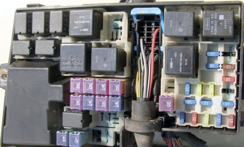
Diagram

Numbers 1 to 6 – a group of fuses in the form of a fuse-link. In the photo, it is closed with a lid.
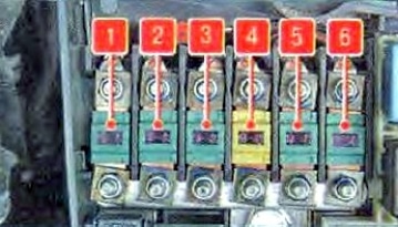
Designation 1
| 1 | 40A IGN2 – Ignition system |
| 2 | 40A BLOWER – Fan electric motor |
| 3 | 60A BTN – Protection of various electrical circuits |
| 4 | 40A FAN 2 – Radiator fan |
| 5 | 40A IGN1 – Ignition system |
| 6 | 40A FAN1 – Radiator fan |
| 7 | 40A P.SEAT – Electric seat |
| 8 | 30A INJ – Fuel injection system |
| 9 | 20А ROOF – Roof hatch |
| 10 | 30A BOSE – Bose Sound System |
| 11 | 30A ENGINE – Engine management system |
| 12 | 20А D.LOCK – Electrically operated locks |
| 13 | 30A P.WIND – Power windows |
| 14 | 30A FUEL PUMP – Fuel pump |
| 14 | 40A IG KEY2 – Ignition system |
| 15 | 40A ABS1 – ABS |
| 16 | 20A ABS2 – ABS |
| 17 | 7.5A DSC – DSC System |
| 18 | 20А FOG – Fog lights |
| 19 | 30A DEF – Heated rear window |
| 20 | 15A TNS – Parking light, license plate light, entrance system light |
| 21 | 10A A / C – Air Conditioning |
| 22 | 20A ETC – Accelerator pedal position sensor |
| 23 | 15A H / LH1 – Headlight range control |
| 24 | 15А DRL – Daytime running light |
| 25 | 15A H / L LO RH – Right low beam headlamp |
| 26 | 15А H / L LO LH – Left low beam headlamp |
| 27 | 7,5А ENG BAR 2 – РСМ (power distribution module) |
| 28 | 10A ECM – Engine management system |
| 29 | 15А ENG BAR 1 – Air flow meter, EGR valve |
| 30 | 20А RWIND2 – Electrically operated glass lifters |
| 31 | 10А STOP – Stop lights |
| 32 | 20А HORN – Sound signal |
| 33 | 25A ENGB + – PCM (power distribution module) |
| 34 | 10А HAZARD – Hazard warning lights, direction indicators |
Designation 2
| 1 | PCS – Pre-emergency safety system |
| 2 | 40A BLOWER – Fan electric motor |
| 3 | 30A FUEL PUMP – Fuel pump |
| 4 | 40A FAN 2 – Radiator fan |
| 5 | 40A IG KEY1 – Ignition system |
| 6 | 40A FAN1 – Radiator fan |
| 7 | 30A P.SEAT (D) – Electric driver’s seat |
| 8 | 30A INJ1 – Fuel injection system |
| 9 | P.SEAT – Electric Passenger Seat |
| 10 | 30A BOSE – Audio system |
| 11 | 30 ENGINE – Engine management system |
| 12 | 20А D.LOCK – Electrically operated locks |
| 13 | 30A P.WIND – Electrically operated glass lifters |
| 14 | 40A IG KEY2 – Ignition system |
| 15 | 40A ABS1 – ABS |
| 16 | 20A ABS2 – ABS |
| 17 | DSC – Vehicle Stability System |
| 18 | 20А Н / L / CLEAN / ROOF – Cleaner of headlights |
| 19 | 30A DEF – Rear defroster |
| 20 | 15A TNS – Parking light, license plate light, entrance system light |
| 21 | 10A A / C – Air Conditioning |
| 22 | 20А TRAILER/TCM – ТСМ |
| 23 | 15А HEAD HI RH – Right high beam headlamp |
| 24 | 15А HEAD HI LH – Left high beam headlamp |
| 25 | 15A HEAD LO RH – Right low beam headlamp |
| 26 | 15А HEAD LO LH – Left low beam headlamp |
| 27 | 20A ETC – Accelerator pedal position sensor |
| 28 | 7,5А ENG BAR 2 – РСМ (power distribution module) |
| 29 | 10A ECM – Engine management system |
| 30 | 10A INJ1 – Fuel injection system |
| 31 | 15А ENG BAR 1 – Air flow meter, EGR valve |
| 32 | 15А FOG – Fog lights |
| 33 | 10А STOP – Stop lights |
| 34 | 20А HORN – Sound signal |
| 35 | 25A ENGB + – PCM (power distribution module) |
| 36 | 10А HAZARD – Hazard warning lights, direction indicators |
Relay
| R4 | Heated rear window relay |
| R5 | Lighting lamp circuit control relay |
| R6 | Реле drive-by-wire |
| R7 | Headlight relay |
| R8 | Back-up headlight relay |
| R9 | Fuel pump relay |
| R10 | Starter relay No. 2 |
| R11 | Cooling fan relay # 2 |
| R12 | Fan relay |
| R13 | Fuel pump speed control relay |
| R14 | Injector relay |
| R15 | Starter relay No. 1 |
| R16 | Main relay |
| R17 | Cooling fan relay # 1 |
Relay Box Diagram

Assignment
- Rear fog lamp relay
- Fog lamp relay
- Air conditioner relay
- Horn relay
- Brake light relay


