BlogFuse Box DiagramMazda FDB
2014-2019 Mazda3 Fuse Box Diagram
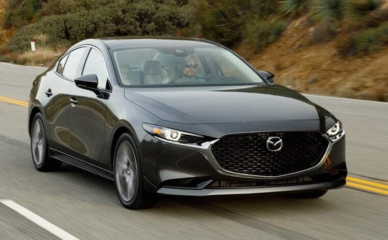
2014-2019 Mazda3 fuse box diagram, location, rating and replacement, (BM-3rd generation).
Mazda3 Fuse Box Diagram: Passenger compartment fuse box
It is located at the bottom of the left pillar, on the driver’s side, behind the protective cover. To access the block, it must be moved in the direction of the arrow.

For example

Diagram
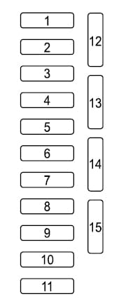
Assignment
| 1 | 30A P.SEAT D – Seat adjustment |
| 2 | 25А D.LOCK – Central locking |
| 3 | 25А P.WINDOW2 – Power windows |
| 4 | 20А SEAT WARM – Heated seats |
| 5 | 15A R.OUTLET3 – Additional power sockets |
| 6 | 15A SRS2 / ESCL – Seat load sensor |
| 7 | 10A SUNROOF – Luke |
| 8 | 7.5A M.DEF – Heated rear-view mirrors |
| 9 | 15А R.OUTLET1 – Additional power sockets |
| 10 | 7,5А MIRROR – Adjustment of mirrors |
| 11 | 15А F.OUTLET – Cigarette lighter |
| 12 | 7,5A AT IND – Automatic transmission gear shift indicator |
| 13 | Reserve |
| 14 | Reserve |
| 15 | Reserve |
Fuse number 11 at 15A is responsible for the cigarette lighter.
Mazda3 Fuse Box Diagram: Engine compartment fuse box
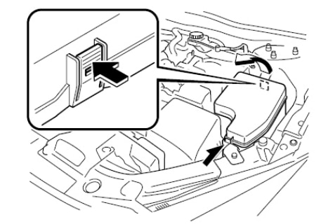
Located on the left side of the engine compartment, next to the battery.

To access, remove the cover
Legend
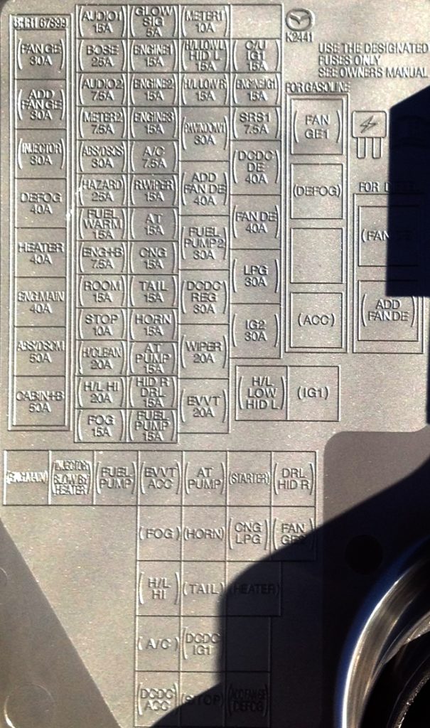
Diagram
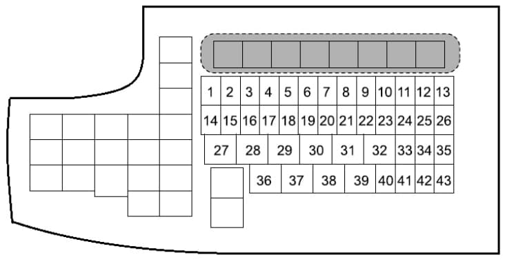
Designation
| 1 | 15А FOG – Fog lights |
| 2 | 20А H / L HI – High beam headlamps |
| 3 | 20А H / CLEAN – Headlight washer |
| 4 | 10A STOP – Brake lights |
| 5 | 15A ROOM – Additional light (overlays) |
| 6 | 7,5А ENG + B – Engine management system |
| 7 | FUEL WARM – fuel heating |
| 8 | 25A HAZARD – Hazard warning system, direction indicators |
| 9 | 30A ABS / DSCS – ABS, Dynamic Stability Control System |
| 10 | 7,5A METER2 – Instrument cluster |
| 11 | 7.5A AUDIO2 – Audio system second option |
| 12 | 25A BOSE – Bose® Audio System (if equipped) |
| 13 | 15A AUDIO1 – Audio system first option |
| 14 | 15A FUEL PUMP – Fuel system, fuel pump |
| 15 | 15A HID R DRL – Right headlight (RH) * 1, Daytime running lights |
| 16 | 15A AT PUMP – transmission control system |
| 17 | 15А HORN – Signal, horn |
| 18 | 15А TAIL – Rear lights, license plate lights, parking lights, front side marker lights |
| 19 | Reserve |
| 20 | 15А AT- TRANSAXLE control systems |
| 21 | 15А R.WIPER – Rear wiper |
| 22 | 7.5A A / C – Air Conditioning |
| 23 | 15A ENGINE3 – Engine management system |
| 24 | 15A ENGINE2 – Engine management system |
| 25 | 15A ENGINE1 – Engine management system |
| 26 | 5A GLOW SIG – Engine Management |
| 27 | 20А EVVT – Engine management system |
| 28 | 20А WIPER – Washer and cleaner for front glass |
| 29 | 30A DCDC REG -To protect various circuits |
| 30 | Reserve |
| 31 | 40А ADD FAN DE – Cooling fan |
| 32 | 30А P.WINDOW1 – Power windows |
| 33 | 15A H / L LOW R – Low beam headlamp, right (RH) * 2 |
| 34 | 15A H / L LOW L HID L – Headlamp left (LH) * 1, Headlamp low beam left (LH) * 2 |
| 35 | 10A METER1 – Instrument panel |
| 36 | 30A IG2 – For the protection of various circuits |
| 37 | Reserve |
| 38 | 40А ADD FAN DE – Cooling fan |
| 39 | 40A DCDC DE – To protect additional circuits |
| 40 | 7.5A SRS1 – Airbag |
| 41 | 15A ENGINE. IG1 – Engine management system |
| 42 | 15A C / U IG1 – For the protection of various circuits |
| 43 | Reserve |


