BlogFuse Box DiagramHonda FBD
2006-2011 Honda Civic Fuse Box Diagram
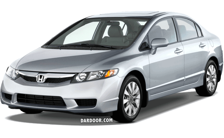
2006-2011 Honda Civic and Honda Civic Hybrid fuse box diagram (fuse layout), location, and assignment of fuses and relays for models MK8 (FA/FD/FG/FK/FN).
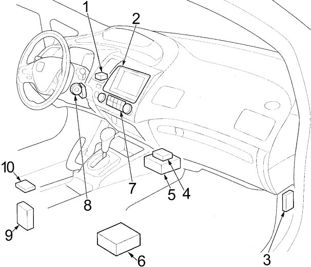
2006-2011 Honda Civic Fuse Box Diagram: Passenger Compartment
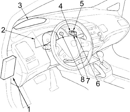
- Fuse Box
- Gauge Control Module (Tach)
- Gauge Control Module (Speedo)
- Except for GX: Console Accessory Power Socket Relay
- Hybrid: Front Accessory Power Socket Relay
- GX: Starter Control Relay
- Except for GX: Front Accessory Power Socket Relay
- Hybrid: Console Accessory Power Socket Relay
- GX: Console Accessory Power Socket Relay
- GX: Front Accessory Power Socket Relay
- GX: Injector Control Module Relay
- SL (2009-2011): Fog Light Relay
- 2008-2011: Tire Pressure Monitoring System (TPMS) Control Unit
- Audio/Navigation Unit or Audio Unit
- Electric Power Steering (EPS) Control Unit
- GX: Injector Control Module
- 2-Door: Audio Amplifier
- Supplemental Restraint System (SRS) Unit
- 2009-2011: USB Adapter Unit
- Heating, Ventilation, and Air Conditioning System (HVAC) Control Unit or Heater Control Panel
- Immobilizer-Keyless Control Unit
- 2009-2011: HandsFreeLink Control Unit
- 4-Door: Audio Amplifier
Instrument Panel Fuse Box Diagram
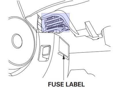
The interior fuse box is underneath the steering column.
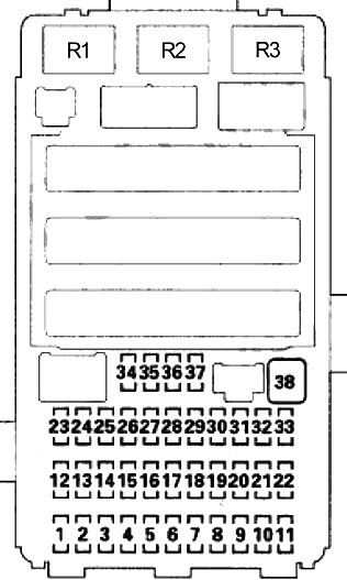
| № | A | Protected Component |
|---|---|---|
| 1 | 7.5 | Power Mirror Switch Light (4-Door), Power Window Relay (without Key-off Operation) |
| 2 | 15 | except for Hybrid: Camshaft Position (CMP) Sensor A, Engine/Powertrain Control Module (ECM/PCM), Immobilizer-Keyless Control Unit |
| 15 | Hybrid: Powertrain Control Module (PCM), Fuel Pump (PGM-FI Main Relay №2), Immobilizer-Keyless Control Unit | |
| 3 | 10 | Alternator, Engine/Powertrain Control Module (ECM/PCM), Evaporative Emission Control (EVAP) Canister Purge Valve, EVAP Canister Vent Shut Valve, Mass Air Flow (MAF) Sensor |
| 10 | DC-DC Converter, Electrical Load Detector (ELD), Evaporative Emission Control (EVAP) Canister Purge Valve, Mass Air Flow (MAF) Sensor, Powertrain Control Module (PCM), Brake Pedal Position Switch, Secondary Heated Oxygen Sensor (HO2S) | |
| 4 | 7.5 | ABS or VSA Modulator-Control Unit, Yaw Rate-Lateral Acceleration Sensor (with VSA), Electric Power Steering (EPS) Control Unit |
| 5 | 15 | 2-Door: Audio Amplifier |
| 15 | Driver’s Seat Heater, Front Passenger’s Seat Heater, Seat Heater Relay | |
| 6 | – | – |
| 7 | 7.5 | Tire Pressure Monitoring System (TPMS) Control Unit |
| 8 | – | – |
| 9 | 7.5 | Occupant Detection System (ODS) Unit, Supplemental Restraint System (SRS) Unit, Passenger’s Airbag Cut-Off Indicator |
| 10 | 7.5 | Gauge Control Module (Tach), Power Window Master Switch (2-Door with Auto Up/Auto Down), Back-Up Light Switch (M/T), Shift Lock Solenoid (A/T), Multiplex Integrated Control Unit (MICU), Tire Pressure Monitoring System (TPMS) Control Unit, BCM Module (Hybrid), Interface Box |
| 11 | 10 | Supplemental Restraint System (SRS) Unit |
| 12 | 10 | Right Headlight (High Beam) |
| 13 | 10 | Left Headlight (High Beam) |
| 14 | 7.5 | Audio Unit Light, Dash Lights Brightness Controller Light, Hazard Warning Switch Light, Heater Control Panel Light/HVAC Control Unit Light, Moonroof Switch Light, Passenger’s Airbag Cut-Off Indicator, Select/Reset Switch Light, A/T Gear Position Indicator Panel |
| Light, Audio Remote Switch Light, Cruise Control Combination Switch Light, Driver’s Seat Heater Switch Light, HFL-Voice Control | ||
| Switch Light, Interface Box, Passenger’s Seat Heater Switch Light, VSA OFF Switch Light | ||
| 15 | 7.5 | Parking Lights, Taillights, License Plate Lights, Side Marker Lights |
| 16 | 10 | Right Headlight (Low Beam) |
| 17 | 10 | Left Headlight (Low Beam) |
| 18 | 20 | High Beam, Multiplex Integrated Control Unit (MICU) |
| 19 | 15 | Parking Lights, Multiplex Integrated Control Unit (MICU) |
| 20 | – | – |
| 21 | 20 | Low Beam, Multiplex Integrated Control Unit (MICU) |
| 22 | 7.5 | Hybrid: A/C Compressor Driver |
| 23 | 7.5 | Starter Switch Signal, Powertrain Control Module (PCM) |
| 24 | 20 | Moonroof Control/Motor |
| 25 | 20 | Power Door Lock, Multiplex Integrated Control Unit (MICU) |
| 26 | 20 | Driver’s Window Motor (Power Window Master Switch) |
| 27 | – | – |
| 28 | 15 | Rear/Console Accessory Power Socket |
| 29 | 15 | Front Accessory Power Socket |
| 30 | 20 | 4-Door: Front Passenger’s Window Motor |
| 20 | 2-Door: Moonroof Switch, Moonroof Control Unit/Motor, Passenger’s Window Motor | |
| 31 | – | – |
| 32 | 20 | 4-Door: Right Rear Window Motor, Moonroof Switch, Moonroof Control Unit/Motor |
| 33 | 20 | 4-Door: Left Rear Window Motor |
| 34 | – | – |
| 35 | 7.5 | Audio Unit, Front Accessory Power Socket, Rear/Console Accessory Power Socket, Stereo Amplifier (2-Door), HandsFreeLink |
| Control Unit, Ignition Key Switch, Multiplex Integrated Control Unit (MICU), Interface Box | ||
| 36 | 10 | Heater Control Panel/HVAC Control Unit, Power Mirrors, Recirculation Control Motor, A/C Compressor Clutch Relay, Blower Motor Relay, Power Mirror Defogger Relay, Rear Window Defogger Relay, Cooling Fan Control Relay and Radiator Ran Relay (A/C Diode), AHB Buzzer (Hybrid), Servo Unit (Hybrid) |
| 37 | 7.5 | Daytime Running Light, Multiplex Integrated Control Unit (MICU) |
| 38 | 30 | Front Wiper, Multiplex Integrated Control Unit (MICU) |
| R1 | Power Window | |
| R2 | Fuel Pump (PGM-FI Main 2) | |
| R3 | Starter Cut | |
Engine Compartment
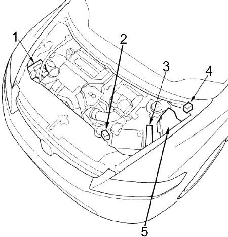
- ABS or VSA Modulator Control Unit
- Hybrid: Fuse Box №2
- Engine / Powertrain Control Module (ECM/PCM)
- Hybrid: Servo Unit
- Fuse Box №1
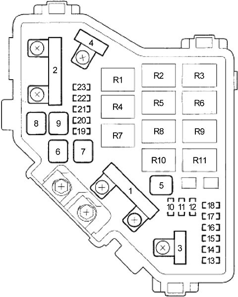
Fuse Box №1 Diagram
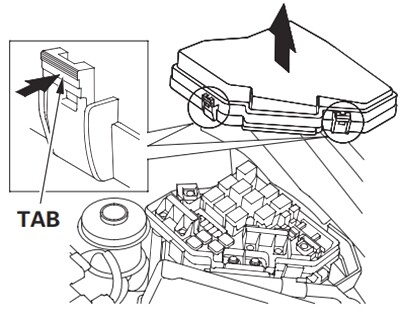
The under-hood fuse box is on the driver’s side, next to the brake fluid reservoir. To open it, push the tabs as shown.
| № | A | Protected Component |
|---|---|---|
| 1 | 100 | Battery, Power Distribution |
| 70 | Electric Power Steering (EPS) Control Unit | |
| 2 | 50 | Ignition Switch |
| 80 | except Hybrid: Fuses (Passenger Compartment): 5, 6, 7, 27, 28, 29, 31 | |
| 80 | 2006-2007 (Hybrid): Fuses (Passenger Compartment): 5, 6, 7, 27, 28, 29, 31 | |
| 60 | 2008-2011 (Hybrid): Fuses (Passenger Compartment): 5, 6, 7, 27, 28, 29, 31 | |
| 3 | 30 | ABS or VSA Modulator-Control Unit |
| 30 | except Hybrid: ABS or VSA Modulator-Control Unit | |
| 30 | Hybrid: ABS Modulator-Control Unit | |
| 40 | Hybrid: VSA Modulator-Control Unit | |
| 4 | 50 | Fuses (Passenger Compartment): 18, 19, 20, 21 |
| 40 | Fuses (Passenger Compartment): 24, 25, 26, 30, 32, 33 | |
| 5 | 40 | Servo Unit |
| 6 | 20 | A/C Condenser Fan Relay, A/C Condenser Fan Motor |
| 7 | 20 | M/T: Radiator Fan Relay, Radiator Fan Motor |
| 30 | A/T: Radiator Fan Relay, Radiator Fan Motor | |
| 8 | 30 | 4-Door: Rear Window Defogger Relay, Rear Window Defogger |
| 40 | 2-Door: Rear Window Defogger Relay, Rear Window Defogger | |
| 9 | 40 | Blower Motor Relay, Blower Motor |
| 10 | 10 | Hazard Lights, Multiplex Integrated Control Unit (MICU), Gauge Control Module (Speedo), Gauge Control Module (Tach), |
| 11 | 15 | Air Fuel Ratio (A/F) Sensor №1, Engine/Powertrain Control Module (ECM/PCM), Vent Shut Solenoid (Hybrid) |
| 12 | 15 | Brake lights, Engine/Powertrain Control Module (ECM/PCM), Horn, Multiplex Integrated Control Unit (MICU) |
| 13 | 15 | Hybrid: Rear Ignition Coils |
| 14 | 15 | Hybrid: Front Ignition Coils |
| 15 | 7.5 | A/C Condenser Fan Relay |
| 16 | – | – |
| 17 | 15 | 2-Door: Audio Amplifier |
| 18 | 15 | except Hybrid: Iqnition Coils, Engine/Powertrain Control Module (ECM/PCM) |
| 20 | Hybrid: Iqnition Coils, Powertrain Control Module (PCM) | |
| 19 | 15 | Crankshaft Position (CKP) Sensor, Camshaft Position (CMP) Sensor B, Engine/Powertrain Control Module (ECM/PCM), Electronic Throttle Control System (ETCS) Control Relay, Injectors, PGM-FI Main Relay №1 (Fl MAIN), PGM-FI Main Relay №2 (Fuel Pump) (except Hybrid) |
| 20 | 7.5 | A/C Compressor Clutch Relay, A/C Compressor Clutch |
| 21 | 15 | Electronic Throttle Control System (ETCS) Control Relay, Engine/Powertrain Control Module (ECM/PCM) |
| 22 | 7.5 | Ceiling Light, Map Lights, Trunk Light, Auxiliary Electric Water Pump, Auxiliary Electric Water Pump Relay |
| 23 | 10 | Audio Unit, Data Link Connector (DLC), Gauge Control Module (Tach), Gauge Control Module (Speedo), Hazard Warning Switch, Immobilizer-Keyless Control Unit, Multiplex Integrated Control Unit (MICU), Motor Control Module (MCM) (Hybrid), BCM Module (Hybrid), HandsFreeLink Control Unit |
| R1 | Radiator Fan | |
| R2 | A/C Condenser Fan | |
| R3 | Fan Control | |
| R4 | Electronic Throttle Control System (ETCS) Control | |
| R5 | Blower Motor | |
| R6 | Power Mirror Defogger | |
| R7 | PGM-FI Main (№1) | |
| R8 | Rear Window Defogger | |
| R9 | PGM-FI Subrelay | |
| R10 | A/C Compressor Clutch | |
| R11 | Ignition Coil | |
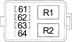
Fuse Box №2 Diagram
| № | A | Protected Component |
|---|---|---|
| 61 | 10 | BCM Module, Motor Control Module (MCM) Relay №2, Servo Unit |
| 62 | 7.5 | BCM Module, Motor Control Module (MCM) Relay №1 |
| 63 | 15 | Servo Unit |
| 64 | – | – |
| R1 | Auxiliary Electric Water Pump | |
| R2 | Fuel Pump | |


