2021-2022 Hyundai Santa Fe Fuse Box Diagrams, relays, wiring, location, rating, assignment, rating and replacement.
Fuses and Relay
- Any vehicle’s electrical system usually is protected by fuses.
- This car has 5 fuse panels, one located in the driver’s side panel bolster, the others are in the engine compartment.
- If any of your vehicle’s lights, accessories, or controls do not function, check the appropriate circuit fuse.
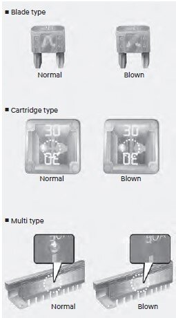
- If a fuse has blown, the element inside the fuse will be melted or broken.
- If the electrical system does not work, first check the driver’s side fuse panel.
- Before replacing a blown fuse, turn the engine and all switches off, and then disconnect the negative battery cable.
- Always replace a blown fuse with one of the same ratings.
- If the replacement fuse blows, this indicates an electrical problem.
- Avoid using the system involved. We recommend that you immediately consult an authorized HYUNDAI dealer.
- Always replace a fuse with the same rating.
- A higher capacity fuse could cause damage and possibly cause a fire.
- Do not install a wire or aluminum foil instead of the proper fuse – even as a temporary repair. It may cause extensive wiring damage and possibly a fire.
- Do not use a screwdriver or any other metal object to remove fuses because it may cause a short circuit and damage the system.
- In case of an emergency, if you do not have a spare fuse, use a fuse of the same rating from a circuit you may not need for operating the vehicle, such as the cigarette lighter fuse.
- If the headlamps or other electrical components do not work and the fuses are undamaged, check the fuse panel in the engine compartment. If a fuse is blown, it must be replaced with the same rating.
- After checking the fuse panel in the engine compartment, securely install the fuse panel cover. You may hear a clicking sound if the cover is securely latched. If it is not securely latched,
electrical failure may occur from water contact. - Not all fuse panel descriptions in this manual may be applicable to your vehicle; the information is accurate at the time of printing. When you inspect the fuse box on your vehicle, refer to the fuse box label and consult the owner’s manual.
Instrument panel fuse replacement
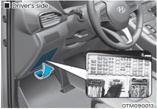
- Turn the vehicle off.
- Turn all other switches off.
- Open the fuse panel cover.
- Refer to the label on the inside of the fuse panel cover to locate the suspected fuse location. Pull the suspected fuse straight out.
- Use the removal tool (Fuse Puller) provided in the engine compartment fuses panel cover.
- Check the removed fuse; replace it if it is blown. Spare fuses are provided in the instrument panel fuse panels (or in the engine compartment fuse panel).
- Push in a new fuse of the same rating, and make sure it fits tightly in the clips. If it fits loosely, consults an authorized HYUNDAI dealer.
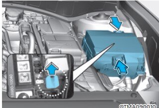
Engine compartment panel fuse replacement
Blade fuse / Cartridge fuse
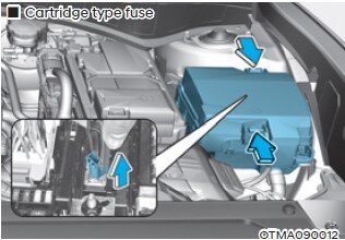
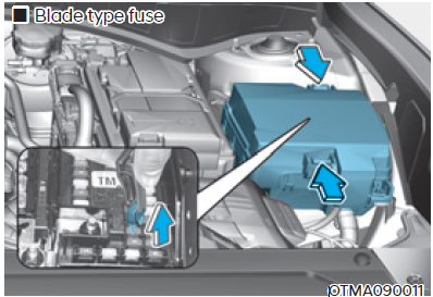
- Turn the vehicle off.
- Turn all other switches off.
- Remove the fuse panel cover by pressing the tap downward and pulling it up.
- Check the removed fuse; replace it if it is blown. To remove or replace the new fuse, use the fuse puller tool in the engine compartment fuse panel.
- Push in a new fuse of the same rating, and make sure it fits tightly in the clips. If it fits loosely, consults an authorized HYUNDAI dealer.
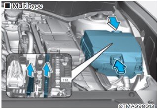
Multi Fuse
If the multi-fuse or midi fuse is blown, consult an authorized HYUNDAI dealer.
Fuse/relay panel description
Instrument panel fuse panel
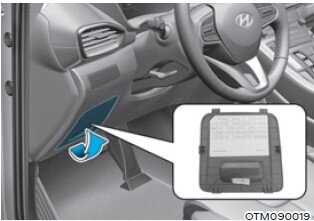
Inside the fuse/relay box cover, you can find the fuse/relay label describing fuse/ relay names and ratings.
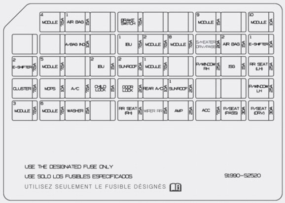
Fuse Name … Fuse Rating … Circuit Protected
MODULE 4 7.5A
Data Link Connector, Stop Lamp Switch, Driver Area Unit
AIR BAG 1 15A
SRS (Supplemental restraint system) Control Module, Passenger Occupant Detection Sensor
BRAKE SWITCH 7.5A
IBU Integrated Body Control Unit), Stop Lamp Switch
MODULE 9 15A
Front A/C Control Module, Driver Door Area Unit, Power Tailgate Module, Low DC-DC Converter, Rear Occupant Alert (ROA) Sensor, Driver IMS Control Module, Head-Up Display, Driver/Passenger Power Outside Mirror
MODULE 10 10A
Blind-Spot Collision Warning Unit LH/RH, Front Wireless Charger
AIR BAG IND. 10A
Overhead Console Assembly, Instrument Cluster
IBU 1 7.5A
IBU (Integrated Body Control Unit )
MODULE 2 7.5A
AC Inverter Outlet, AC Inverter Module, Front Air Ventilation Control Module,
Front Seat Warmer Control Module, 2nd Seat Warmer LH/ RH Control Module
MODULE 8 7.5A
Hazard Switch, Key Solenoid, Mood Lamp, Rain Sensor, Mood Lamp Unit,
Mood Lamp #1/#2
S/HEATER FRT 20A
Data Link Connector, Front Air Ventilation Control Module, Front Seat Warmer Control Module
AIR BAG 2 15A
SRS Control Module
E-SHIFTER1 10A
Electronic Shift Dial
E-SHIFTER2 7.5A
Electronic Shift Dial
MODULE 5 7.5A
Lane Departure Warning Unit, Crash Pad Switch, IBU, Console Switch, 4WD ECM, Surround View Monitor Unit, Upper Console Switch, Parking Collision Avoidance Assist Unit
IBU 2 15A
IBU, Ignition Switch, BLE (Bluetooth Low Energy) Unit, IAU (Identity Authentication Unit), Driver/Passenger Smart Key Outside Handle
SUNROOF 2 20A
Panorama Sunroof
MODULE 1 7.5A
IBU, IAU (Identity Authentication Unit)
P/WINDOW RH 25A
Passenger Safety Power Window Module, Passenger Power Window Switch, Rear Power Window Switch RH, Rear Safety Power Window RH
ISG 15A
Low DC-DC Converter (AMP), Instrument Cluster, Front A/C Control Module, A/V & Navigation Head Unit, Head-Up Display, Audio
RR SEAT(LH) 25A
2nd Seat Warmer LH Control Module, 2nd Seat LH Folding Actuator
CLUSTER 7.5A
Instrument Cluster, Head-Up Display
MDPS 10A
MDPS Unit ❈ MDPS(Motor Driven Power Steering) is the same as EPS(Electric Power Steering).
A/C 7.5A
E/R Junction Block (Blower Relay, PTC Heater Relay)
CHILD LOCK 15A
ICM Relay Box (Child Lock/Unlock Relay)
DOOR LOCK 20A
Door Lock Relay, Door Unlock Relay, Tailgate Relay, Driver Door Unlock Relay
SUNROOF 1 20A
Panorama Sunroof
P/WINDOW LH 25A
Driver Safety Power Window Module, Rear Power Window Switch LH, Rear Safety Power Window LH
MODULE 3 7.5A IBU
MODULE 6 7.5A
Audio, A/V & Navigation Head Unit, A/V & Navigation Keyboard, Front A/C Control Module, Front Wireless Charger, Electro Chromic Mirror, Low DC-DC Converter
WASHER 15A
Multifunction Switch
RR SEAT(RH) 25A
2nd Seat Warmer RH Control Module, 2nd Seat RH Folding Actuator
WIPER RR 15A
Rear Wiper Relay, Rear Wiper Motor
AMP 25A
Low DC-DC Converter (With AMP)
ACC 7.5A
IBU, Front USB Charger, Low DC-DC Converter, Rear USB Charger LH/RH, IAU (Identity Authentication Unit)
P/SEAT (PASS) 30A
Passenger Seat Manual Switch
P/SEAT (DRV) 30A
Driver IMS Control Module, Driver Seat Manual Switch
Engine compartment fuse panel (Engine room junction block)
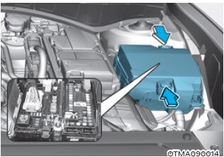
Inside the fuse/relay box cover, you can find the fuse/relay label describing fuse/ relay names and ratings.
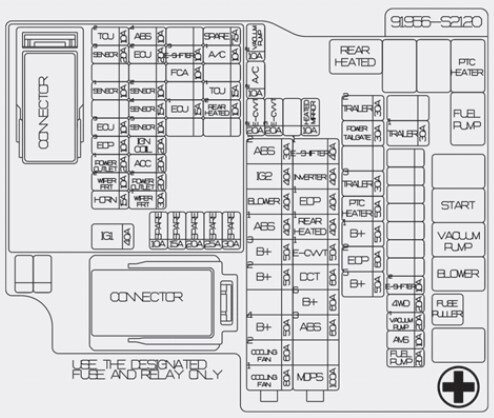
MULTI FUSE 1 (10P)
COOLING FAN1 80A
COOLING FAN2 60A
[BLDC 400W] Cooling Fan ControllerB+4 50A
ICU Junction Block (Fuse – MODULE8, SUNROOF1, AMP, P/WINDOW RH, S/HEATER DRV/PASS)
B+2 50A
ICU Junction Block (IPS 8 SPOC+/IPS 10/IPS 11/ IPS 13/IPS 14/IPS 15)
B+3 50A
ICU Junction Block (Fuse – E-SHIFTER1, P/ SEAT (DRV, P/SEAT (PASS), P/WINDOW LH, RR SEAT(LH))
BLOWER 40A
Blower Relay
IG2 40A
Start Relay, PCB Block (PDM (IG2) Relay)
ABS 2 30A
ESC Module
MULTI FUSE 2 (10P)
MDPS 100A MDPS Unit ❈ MDPS(Motor Driven Power Steering) is the same as EPS(Electric Power Steering).
ABS 3 60A
ESC Module
B+6 60A
PCB Block (B+)
DCT 60A
TCM
E-CVVT1 50A
PCB Block (E-CVVT Relay)
REAR HEATED 40A
Rear Heated Relay
INVERTER 40A
AC Inverter Module
E-SHIFTER 1 40A
SCU
FUSE
HEATED MIRROR 10A
Rear Heated Relay, Driver/Passenger Outside Mirror, Front A/C Control Module
E-CVVT3 20A
PCM, PCB Block (E-CVVT Relay)
E-CVVT2 20A
PCM, PCB Block (E-CVVT Relay)
A/C2 10A
Blower Relay, Front A/C Control Module
VACUUM PUMP2 10A
ESC Module, Vacuum Pump Relay, Vacuum Pump
B+5 50A
ICU Junction Block (Fuse – DOOR LOCK, IBU1, IBU2, BRAKE SWITCH, CHILD LOCK, RR SEAT(RH), SUNROOF2)
EOP2 60A
[G4KP] Electronic Oil Pump
B+1 50A
ICU Junction Block (IPS 1 SPOC+/IPS 2/IPS 3/IPS 5/IPS 6/IPS 7/Long Term Load Latch Relay, Short Term Load Latch Relay)
PTC HEATER 50A
PTC (Positive Temperature Coefficient) Heater Relay
TRAILER3 30A
Trailer Module
POWER TAILGATE 30A
Power Tail Gate Unit
TRAILER2 30A Trailer Module
FUEL PUMP 20A Fuel Pump Relay
AMS 10A Battery Sensor
VACUUM PUMP1 20A Vacuum Pump Relay
4WD 20A 4WD ECM
E-SHIFTER2 10A SCU
TRAILER1 30A Trailer Module


