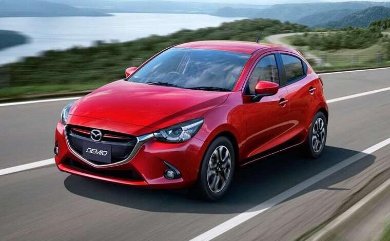
2008-2016 Mazda2 fuse box diagram, wiring, rating, replacement and location (DE – 3rd generation)
The number of elements in boxes may differ and depends on the year of manufacture, the region of delivery and the level of equipment. Check with your diagrams or other technical documentation.
2008-2016 Mazda2 Fuse Box Diagram: Fuse Boxes Locations
Layout

Assignment
| 1 | ABS electronic control unit |
| 2 | Heater / A / C blower motor resistor – under dash |
| 3 | Air conditioner electronic control unit |
| 4 | Anti-theft control unit |
| 5 | Accumulator battery |
| 6 | Diagnostic connector (DLC) |
| 7 | The electronic engine control unit |
| 8 | Cooling Fan Motor Resistor – Near Heatsink |
| 9 | Fuse / relay box, engine compartment 1 |
| 10 | Fuse / relay box, engine compartment 2 |
| 11 | Fuse / relay box, engine compartment 3-diesel |
| 12 | Fuse / relay box, instrument panel |
| 13 | Beep 1 |
| 14 | Beep 2 |
| 15 | Keyless entry system control unit |
| 16 | Multifunctional control unit – functions: Fog lights, hazard warning lights, headlights, direction indicators, seat belt monitoring system windshield wipers |
| 17 | Ambient temperature sensor – behind the front bumper |
| 18 | Power steering control unit |
| 19 | SRS electronic control unit |
| 20 | Electronic gearbox control unit – in the engine control unit |
2008-2016 Mazda2 Fuse Box Diagram: Passenger Compartment Fuse Box
It is located at the end of the dashboard behind the protective cover.

Diagram

Assignment
| 1 | 10А TCM – Electronic transmission control unit |
| 2 | 7,5А ILLUMI – Illumination of the instrument panel |
| 3 | 15A CIGAR – Cigar Lighter, Accessory Connector |
| 4 | 7,5А MIRROR – Power mirrors |
| 5 | 7.5A M.DEF – Heated mirrors |
| 6 | S.WARM – Heated seats |
| 7 | 7.5A A / C – Air Conditioning |
| 8 | 20А F.WIP – Windscreen wiper and washer of the front glass |
| 9 | R.WIP – Rear window wiper and washer |
| 10 | STARTER – Starter |
| 11 | METER 2 – Dashboard |
| 12 | 10А ENG – Engine management system |
| 13 | 10A METER – Instrument cluster |
| 14 | 10A SAS – Airbag, DSC |
| 15 | AUDIO 3 – Audio |
| 16 | 30A P / W – Electric windows |
The cigarette lighter fuse is labeled at number 3 at 15A.
Engine compartment fuse box
Engine compartment fuse box
Located on the left side of the engine compartment, next to the battery.

Diagram

Assignment
| 1 | FUEL HEAT – Fuel heating |
| 2 | 15A FUEL PUMP – Fuel pump |
| 3 | 15А F.FOG – Fog lights |
| 4 | 20A P / W – Electric windows |
| 5 | 10А HORN – Signal |
| 6 | 10A EG1 – Engine management system |
| 7 | 30А DSC-P – DSC |
| 8 | 20ADSC-V – DSC |
| 9 | 7,5A MAG Conditioner |
| 10 | 15A TAIL – Tail lights, Sidelights, License plate light |
| 11 | 10A STOP – Stop signals |
| 12 | 7,5A SWS – Airbag |
| 13 | 20A R.DEF – Heated rear window |
| 14 | 10А HAZARD – Warning lamps, direction indicators |
| 15 | 20А D / L – Electric door locks |
| 16 | EOP |
| 17 | 15А ENG BAR – Engine management system |
| 18 | 15A ENGINJ – Engine management system |
| 19 | ENGINJ2 – Engine management system |
| 20 | H / LHI RH – Halogen feet |
| 21 | H / LHI LH – Halogen feet |
| 22 | DCDC3 – Optional Equipment |
| 23 | 15A H / L LO RH – Headlamp (right) |
| 24 | 15А H / L LO LH – Headlamp (left) |
| 25 | AUDIO2 – Audio |
| 26 | DSC-V2 |
| 27 | HORN2 – Signal 2 |
| 28 | METER – Instruments |
| 29 | 15A ROOM – Interior light |
| 30 | GLOW – Candles |
| 31 | EWT |
| 32 | 40A IG KEY 1 – To protect various circuits |
| 33 | FAN 3 – Fan |
| 34 | 30A FAN 2 – Cooling fan |
| 35 | FAN 1 – Fan |
| 36 | INJ – Engine Management |
| 37 | 30A IG KEY 2 – To protect various circuits |
| 38 | 4WD |
| 39 | ABS DSC-P2 – ABS |
| 40 | 30A BLOWER – Air conditioner fan |
Relay
- Reserve
- Glow plug relay
- Engine control relay
- Headlamp high beam relay
- Headlamp low beam relay
- Rear fog lamp relay
- Gasoline: Fuel pump relay
- Heater blower motor relay
- Reserve
- Horn relay
- Air conditioner relay
- Starter relay
- Fog lamp relay
Anything to add? Please write it in the comments.


